Lead Compensators
Definition
Consider a unity feedback system with reference signal
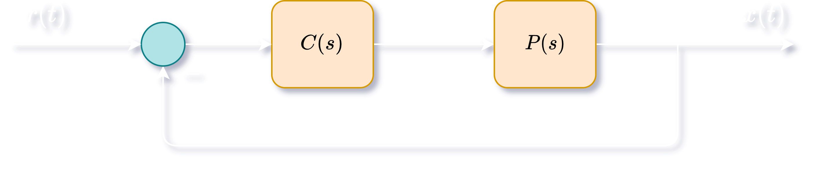
A lead compensator controller
where
By setting
Lead compensation approximates a PD controller, is used to stabilize a system and improve the transient response (i.e improve phase margin).
Design
Steps to design a lead compensator under given specifications:
- Choose
- Find phase margin of
- Find how much extra phase is required to meet the phase margin specification. Set
- Find
- Set
- Check if the compensator achieves the specifications. If not, iterate.
Lag Compensators
Definition
Consider a unity feedback system with reference signal
A lag compensator controller
where
By setting
Lag compensation approximates a PI controller, is used to boost the DC gain.
Design
Steps to design a lead compensator under given specifications:
- Choose
- Find the low frequency gain of
- Choose
- Choose
- Check if the compensator achieves the specifications. If not, iterate.